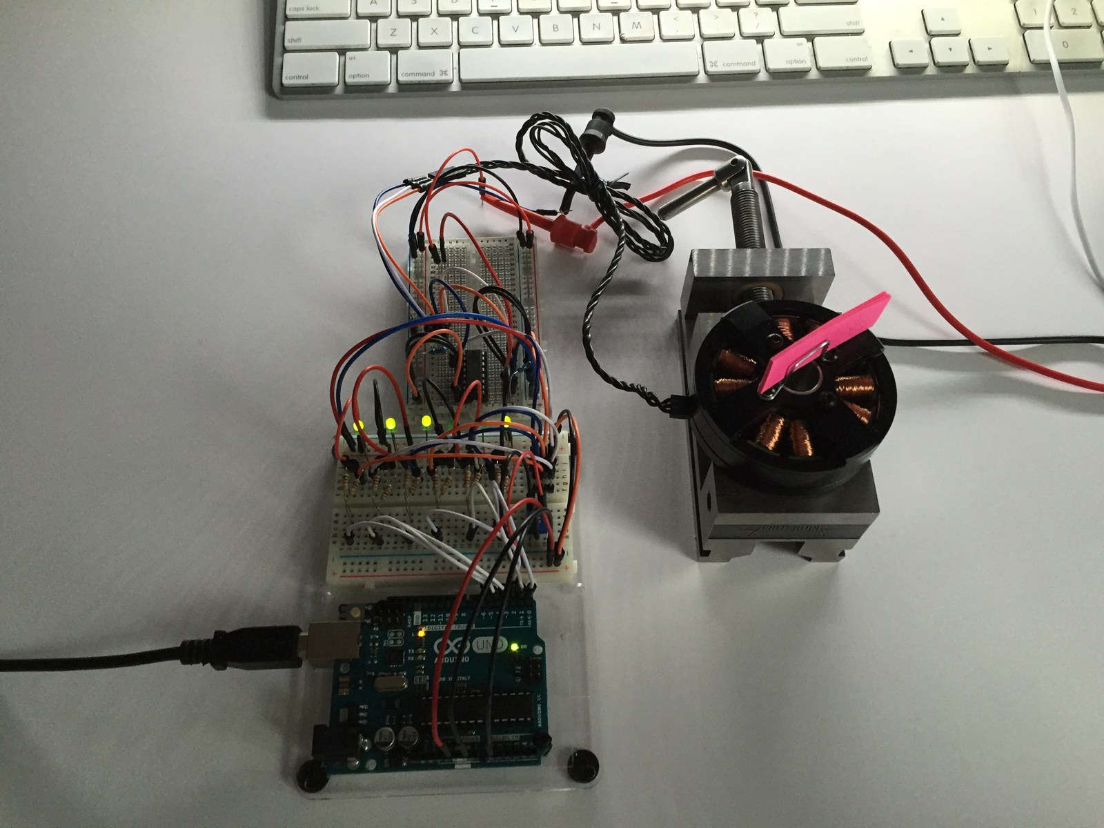
This folder records a low-level brushless motor commutation experiment. Its six-output Arduino sketch is accompanied by a short bench video, a wiring reference and ESC notes. The code is useful for following the sequence of motor-drive states one step at a time.
How the project works
The sketch changes six digital outputs in a repeating six-step sequence. An analog reading from A0 determines the delay between states, so the potentiometer changes the commutation timing directly.
Despite the ESC name, the saved sketch does not send the usual servo-style command pulses to a commercial RC ESC. It also does not measure rotor position or back EMF. It is an open-loop sequence intended to be examined together with its external power-stage circuit.
Hardware and configuration
| Item | In the supplied code |
|---|---|
| Control outputs | Digital pins D0 through D5 |
| Timing control | Analog input A0 |
| Sequence | Six commutation states |
| Timing unit | delay() uses milliseconds |
Working with the supplied code
Review every high/low state against the actual driver circuit. A raw ADC reading can produce a very wide delay range, including zero; add deliberate limits before adapting the experiment to another motor.
Pins D0 and D1 overlap the Uno hardware serial interface. Keep that conflict in mind during upload and debugging. The sketch contains no current limiting or verified switching dead-time control; the motor driver must provide the electrical protection appropriate to the hardware.
Video demonstration
Source code and project files
Browse this project on GitHub. The files below are useful starting points for the sketches and references discussed in this post.
Download the used libraries (ZIP, 14.7 MB).
These notes describe the archived source and project media. The sketches have not been rebuilt or tested on hardware for this article.