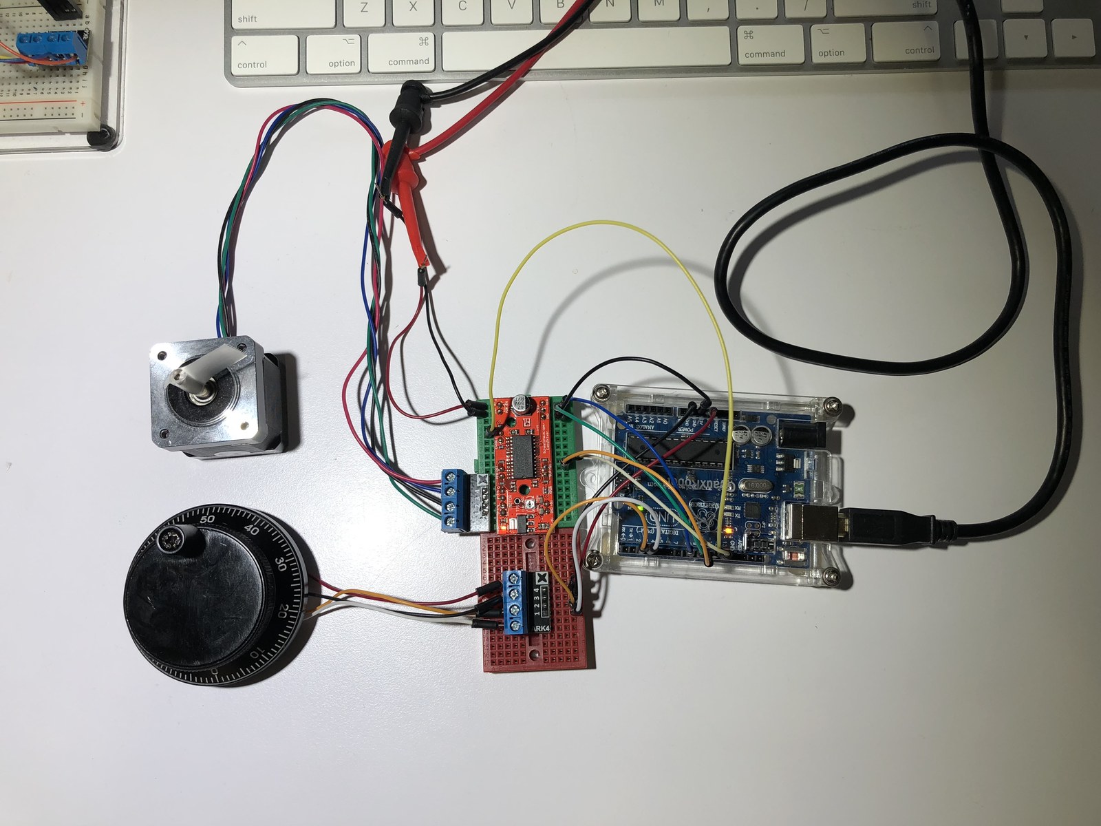
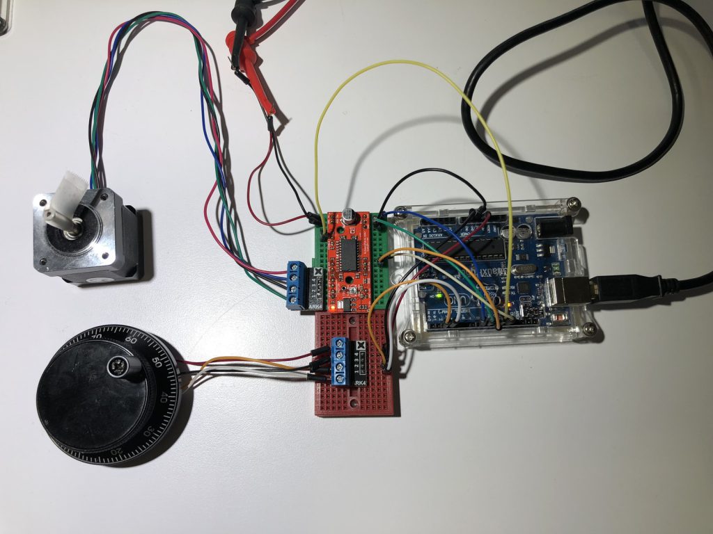
This prototype connects a rotary encoder to an EasyDriver-style step/direction interface. Its photographs and two short recordings document the bench arrangement, while the sketch captures an early version of the encoder-to-motion logic.
How the project works
The encoder uses an interrupt on its CLK input. The main loop consumes the accumulated movement counter and generates step pulses in the selected direction. At startup, it also emits a fixed burst of 200 pulses with 700 microseconds high and 700 microseconds low.
This version contains a return-to-zero block whose button condition is commented out. As saved, the block can run without a button press. That behavior distinguishes it from the later folder 26 variant and should be understood before reproducing the experiment.
Hardware and configuration
| Item | In the supplied code |
|---|---|
| Driver STEP / DIR | D9 / D8 |
| Driver MS1 / MS2 | D10 / D11 |
| Encoder CLK / DT / switch | D2 / D3 / D4 |
| Encoder interrupt | Interrupt 0, FALLING |
Working with the supplied code
Check the driver current limit and motor wiring before applying motion. The SLEEP pin is defined as D12, but this version does not configure it as an output in setup; verify how the actual driver is enabled.
StepsToTake is 3, while the pulse loops count from 1 up to but excluding that value, producing two pulses. Software position changes do not consistently match the generated pulses. The return-to-zero logic is therefore not a calibrated homing system, and the archive should be treated as a development snapshot.
Video demonstration
Source code and project files
Browse this project on GitHub. The files below are useful starting points for the sketches and references discussed in this post.
Download the used libraries (ZIP, 14.7 MB).
These notes describe the archived source and project media. The sketches have not been rebuilt or tested on hardware for this article.