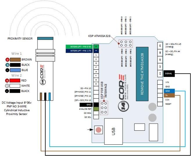
This compact example reads a proximity-sensor interface and switches an indicator output. The folder consists of a short Arduino sketch and a connection diagram, making the relationship between the input test and LED output easy to inspect.
How the project works
The program calls analogRead on channel 1 and turns digital pin 2 on whenever the returned value is greater than zero. Otherwise, it turns the output off. Although a serial port is started, the loop does not print measurements.
The title describes an NPN proximity sensor, but the source does not implement a calibrated detection threshold, hysteresis or explicit active-low handling. Its behavior depends on the signal produced by the complete sensor interface shown in the reference material.
Hardware and configuration
| Item | In the supplied code |
|---|---|
| Input read by the sketch | Analog channel A1 |
| Indicator output | D2 |
| Decision rule | ADC reading greater than zero |
| Serial initialization | 9600 baud; no loop output |
Working with the supplied code
Check the exact sensor’s supply and output type before wiring it. An industrial sensor output may require a pull-up or level interface; do not assume that the sensor supply voltage is suitable for an Arduino input.
For a clearer experiment, first log the input with and without a metal target. Use those observations to choose a meaningful threshold and decide whether digital or analog reading is appropriate. The current comparison accepts even a small nonzero reading, so it should not be described as a tested noise-resistant detector.
Source code and project files
Browse this project on GitHub. The files below are useful starting points for the sketches and references discussed in this post.
Download the used libraries (ZIP, 14.7 MB).
The source and supplied wiring illustration credit 14CORE.
These notes describe the archived source and project media. The sketches have not been rebuilt or tested on hardware for this article.