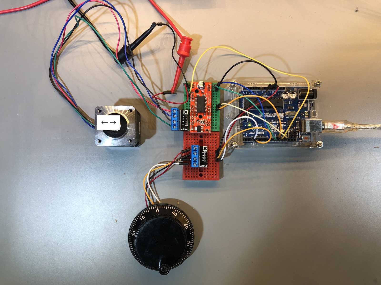
This folder preserves another revision of the encoder-controlled stepper experiment. It shares the EasyDriver pin arrangement with project 24, but changes the handling of the driver sleep signal, encoder debounce and the old return-to-zero routine.
How the project works
The active code produces a startup burst of 200 step pulses, then processes encoder movement to choose a direction and generate further pulses. This version configures SLEEP as an output and includes a 400 microsecond delay in the encoder interrupt routine.
The return-to-zero code is inside a block comment, so the encoder pushbutton does not perform that action in the saved program. A bench video and a photograph show this revision’s motor, encoder and driver arrangement.
Hardware and configuration
| Item | In the supplied code |
|---|---|
| STEP / DIR | D9 / D8 |
| MS1 / MS2 / SLEEP | D10 / D11 / D12 |
| Encoder inputs | CLK D2, DT D3, switch D4 |
| Serial monitor | 9600 baud |
Working with the supplied code
Use this folder when comparing the later behavior with the earlier NEMA prototype; do not combine their sketches into one Arduino build. Confirm the actual driver enable level and microstep mode before testing motion.
The pulse-count mismatch remains: a loop from 1 to less than StepsToTake produces two pulses when the setting is 3. Position bookkeeping also needs review when several encoder events accumulate. Move delays and serial printing out of interrupt handling when developing a more reliable version, and verify travel against the physical axis instead of relying on the software counter alone.
Video demonstration
Source code and project files
Browse this project on GitHub. The files below are useful starting points for the sketches and references discussed in this post.
Download the used libraries (ZIP, 14.7 MB).
These notes describe the archived source and project media. The sketches have not been rebuilt or tested on hardware for this article.