
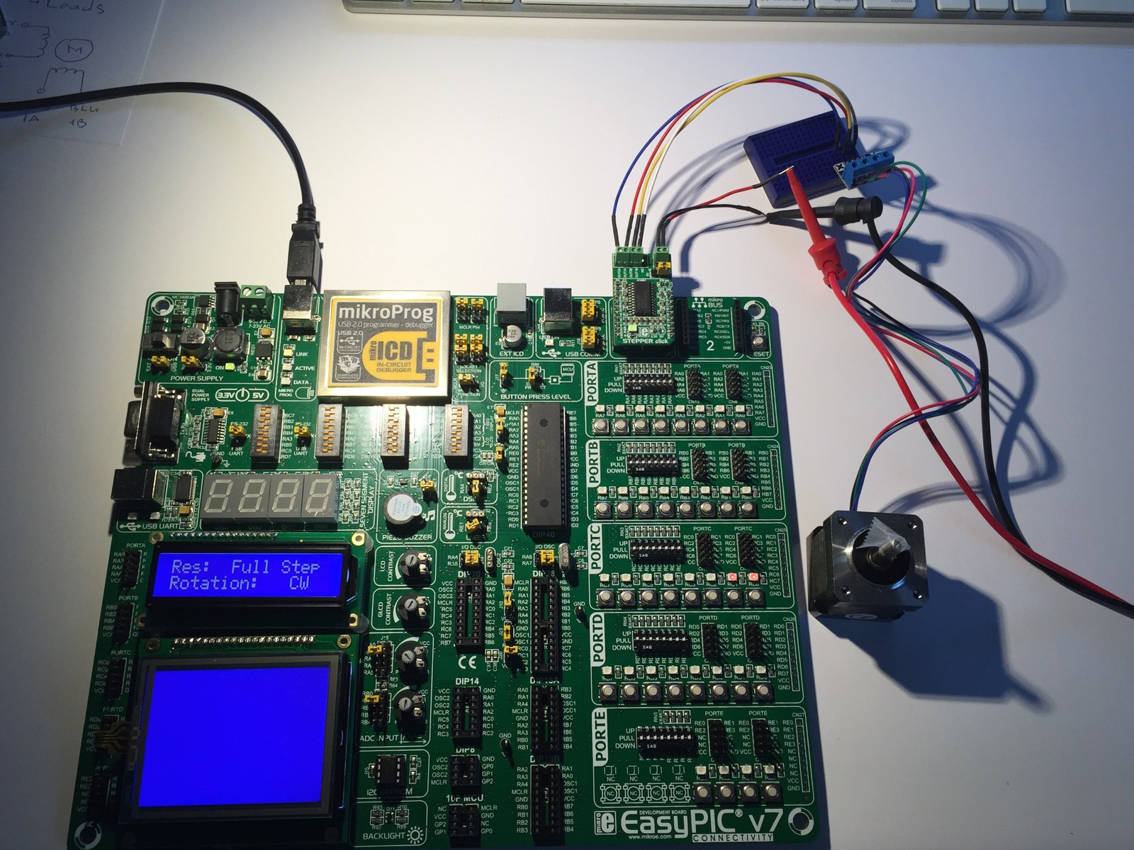
This project uses an EasyPIC7 development board and a Stepper Click driver to explore direction and microstepping from a PIC18F45K22. Two recordings show the board controls and the motor, while the mikroC source documents the signal assignments.
How the project works
The program configures direction, step and microstep-select outputs, then reads board switches to choose full, half, quarter or eighth stepping. Direction inputs select the direction of rotation, and an LCD provides a local interface.
The pulse routine holds STEP low for three milliseconds and high for three milliseconds. Its loop runs from 0 through 2,038 inclusive, producing 2,039 pulses. That pulse count should not be interpreted as a calibrated revolution without accounting for the motor and microstep mode.
Hardware and configuration
| Item | In the supplied code |
|---|---|
| Target | PIC18F45K22 / EasyPIC7 |
| Direction / step | RE0 / RC0 |
| Microstep select | RA2 / RE1 |
| LCD control | RS RB4, EN RB5, data RB0–RB3 |
Working with the supplied code
Open the C file in the matching mikroC PRO for PIC environment and check the board clock, port configuration and LCD connections. The archive also includes a compressed project and board images for reference.
Test one microstep mode at a time and record the number of pulses required for the desired travel. Driver current settings and motor supply belong to the driver setup, while the PIC code determines the logic signals and timing.
Video demonstrations
Source code and project files
Browse this project on GitHub. The files below are useful starting points for the sketches and references discussed in this post.
Download the used libraries (ZIP, 14.7 MB).
These notes describe the archived source and project media. The sketches have not been rebuilt or tested on hardware for this article.