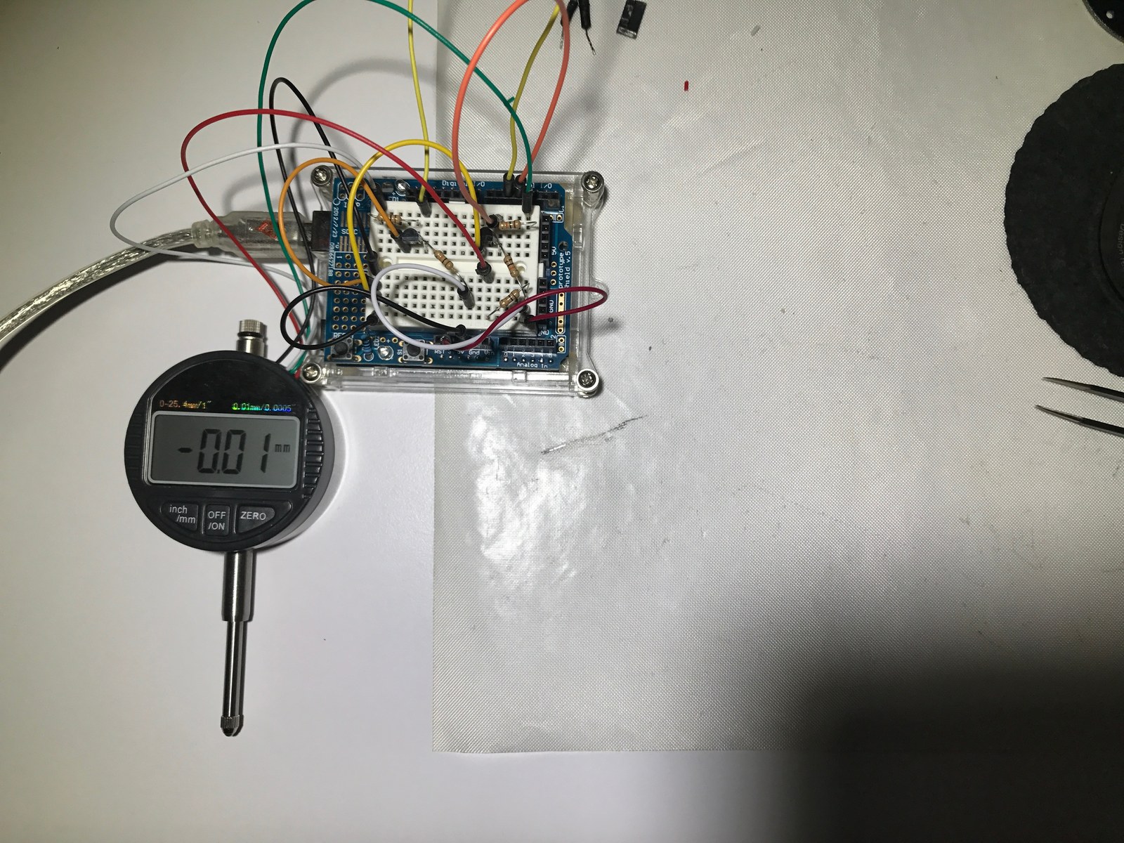
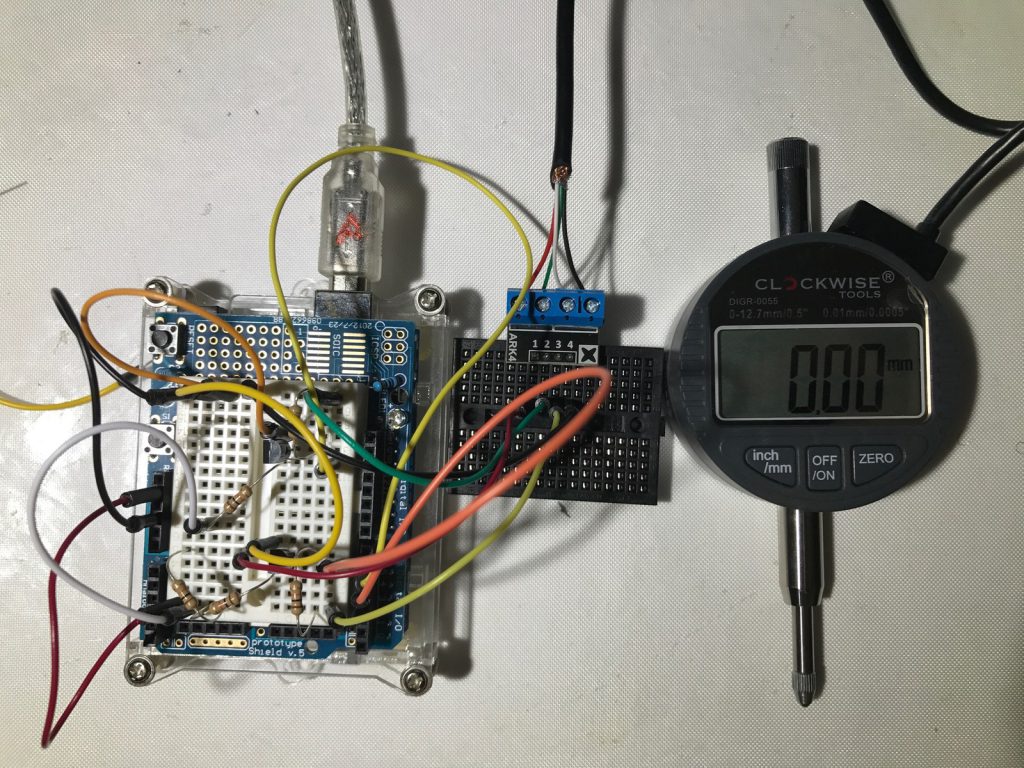
This project decodes the clock and data signals from a digital measuring instrument and prints the result on an Arduino serial connection. The archive’s photographs show a digital indicator; the caliper-port and level-shifter references explain the related interface experiment.
How the project works
The sketch looks for a clock interval longer than 500 microseconds to identify a new sequence, then reads 23 bits. Low data levels set bits in a 20-bit value, and bit 20 selects a negative sign.
The assembled number is divided by 100 and printed with two decimal places. That conversion belongs to the protocol expected by this particular sketch; it does not establish that every digital caliper or indicator uses the same format or units.
Hardware and configuration
| Item | In the supplied code |
|---|---|
| Clock input | D4 |
| Data input | D5 |
| Serial monitor | 9600 baud |
| Output | Signed value / 100, two decimal places |
Working with the supplied code
Identify the instrument’s signal voltage before connecting it to the Arduino. The supplied transistor level-shifter drawing is relevant because low-voltage measuring instruments cannot be assumed to tolerate a direct 5 V connection.
The code uses blocking waits for every clock transition. An unplugged instrument can therefore leave it waiting indefinitely. Add timeouts and verify the bit order, polarity and scale against known positions before using the readings in a machine display or data logger. On AVR targets, review the width of the 1 << i expression when assembling bits beyond the 16-bit int range.
Video demonstration
Source code and project files
Browse this project on GitHub. The files below are useful starting points for the sketches and references discussed in this post.
Download the used libraries (ZIP, 14.7 MB).
These notes describe the archived source and project media. The sketches have not been rebuilt or tested on hardware for this article.