
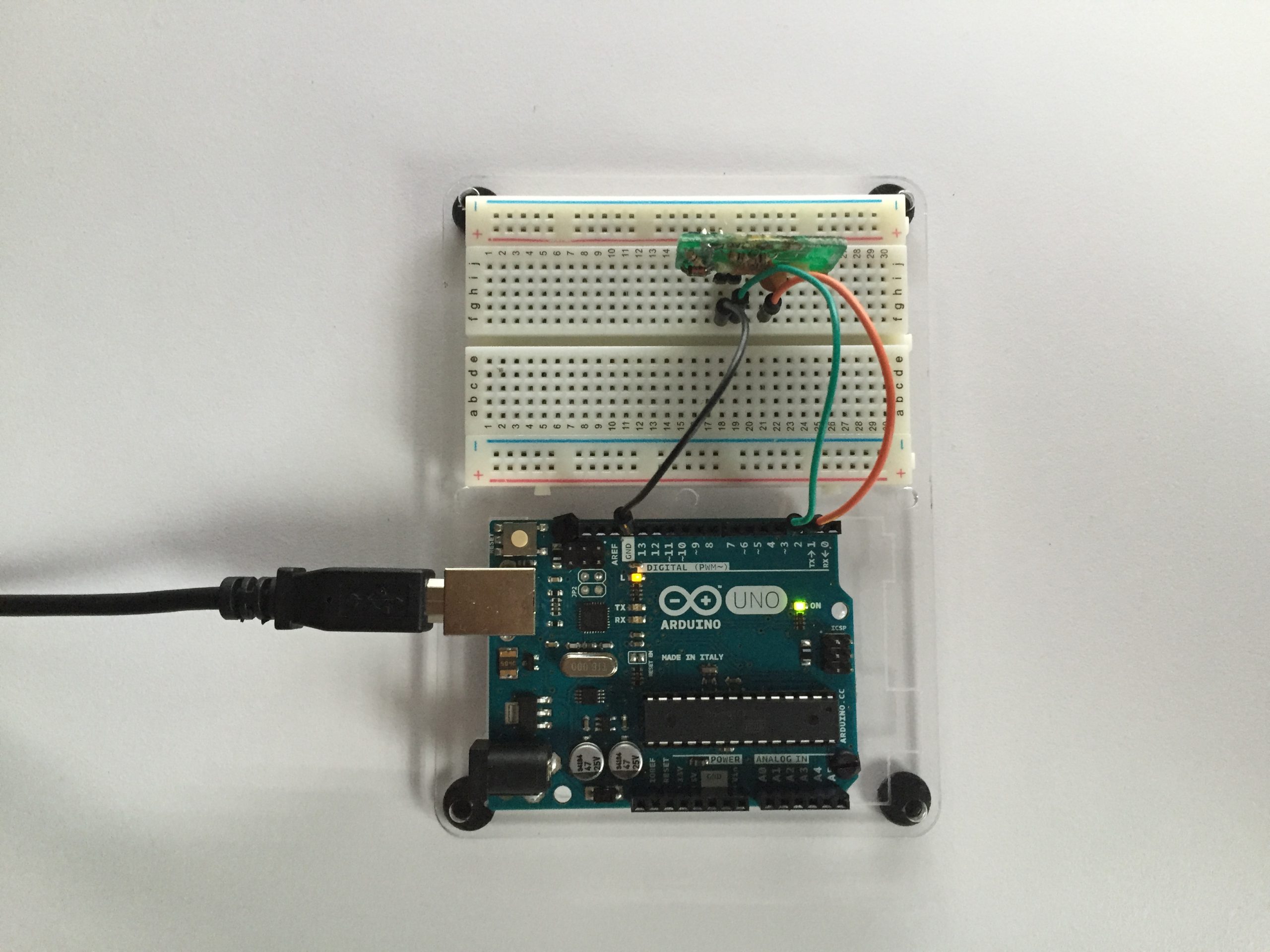
Controlling X10 Devices using Arduino and X10 Firecracker device
This project connects an Arduino Uno to the X10 CM17A Firecracker so an Arduino sketch can send lighting and appliance-control commands. The prototype uses two digital outputs and a ground connection, with photographs showing the original connector pinout and a compact breadboard version.
The Firecracker transmits commands by radio to an X10 transceiver, which passes them on to compatible X10 modules. A receiver such as the TM751 and suitable lamp or appliance modules are therefore part of the setup. See X10’s CM17A documentation for the manufacturer’s system requirements.
See it in action
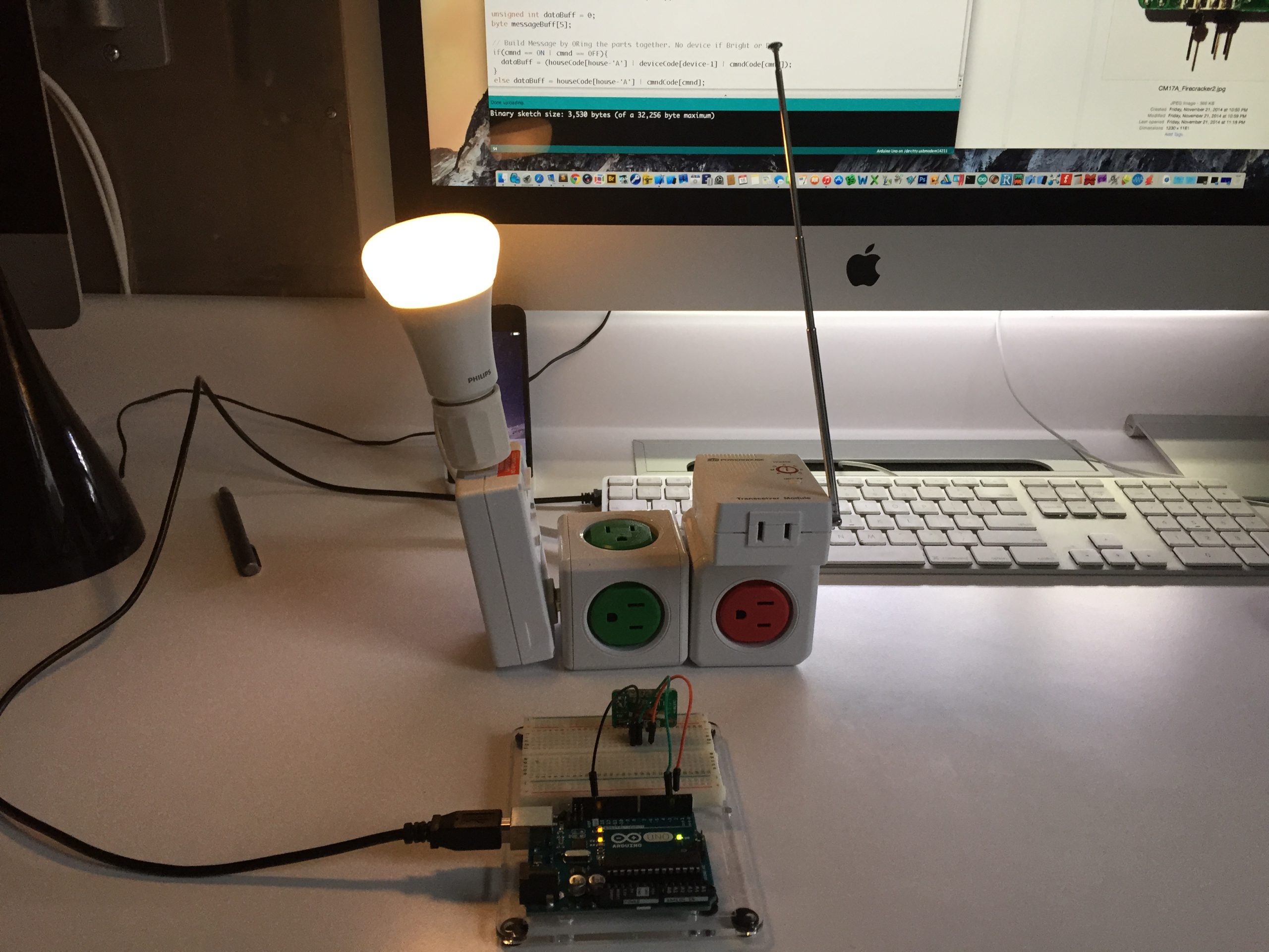
The original demonstration shows the Arduino, Firecracker, X10 modules, and a lamp working together.
What you need
- An Arduino Uno, as used in the photographed prototype, and a USB cable.
- An X10 CM17A Firecracker interface.
- A compatible X10 RF transceiver and a lamp or appliance module; dimming requires a module and lamp that support it.
- A breadboard, jumper wires, and access to the Firecracker’s RTS, DTR, and ground connections.
- The
Arduino_To_CM17A.inosketch from the project resources.
Connect the Arduino to the CM17A
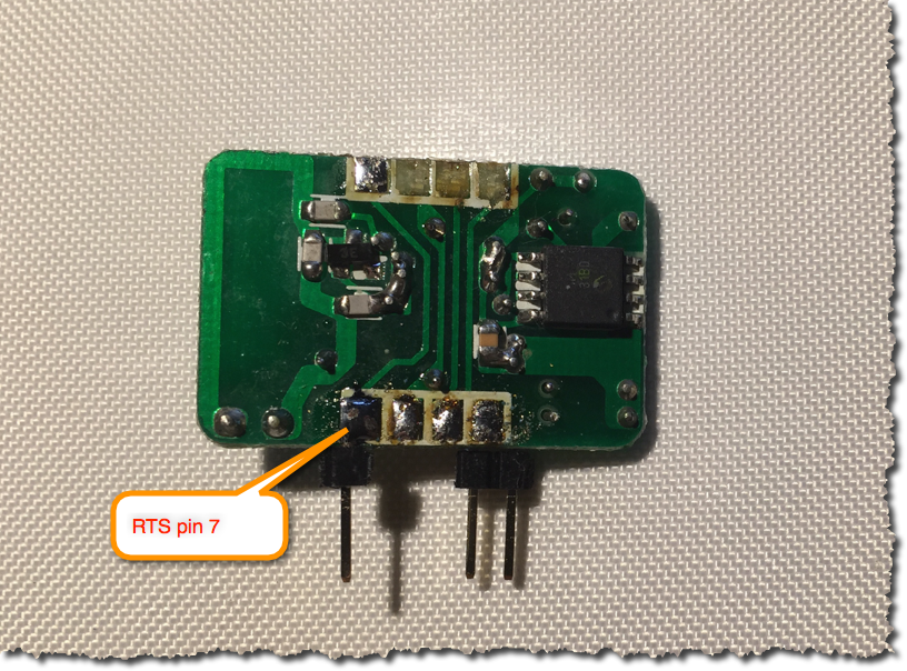
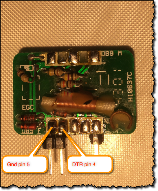
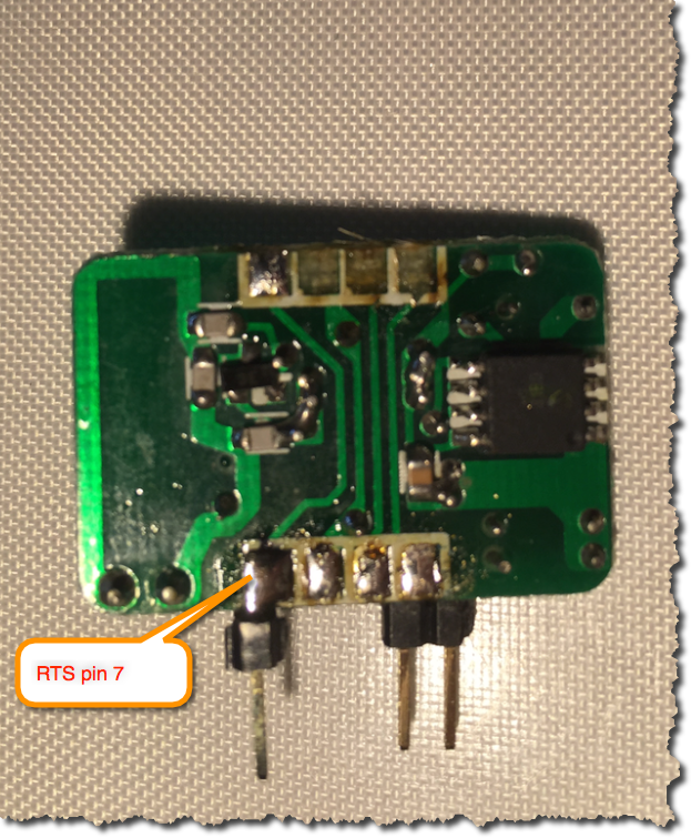
The supplied sketch assigns Arduino digital pin 2 to RTS and digital pin 3 to DTR. Its connection comments and the annotated photographs identify the following DB9 pins:
| Arduino Uno | CM17A signal | DB9 pin |
|---|---|---|
| Digital pin 2 | RTS | 7 |
| Digital pin 3 | DTR | 4 |
| GND | Ground | 5 |
Use the connector’s pin numbers when checking the wiring: the apparent left-to-right order changes when viewed from the opposite side. The original project uses the Uno’s 5 V logic and does not include a MAX232 interface.
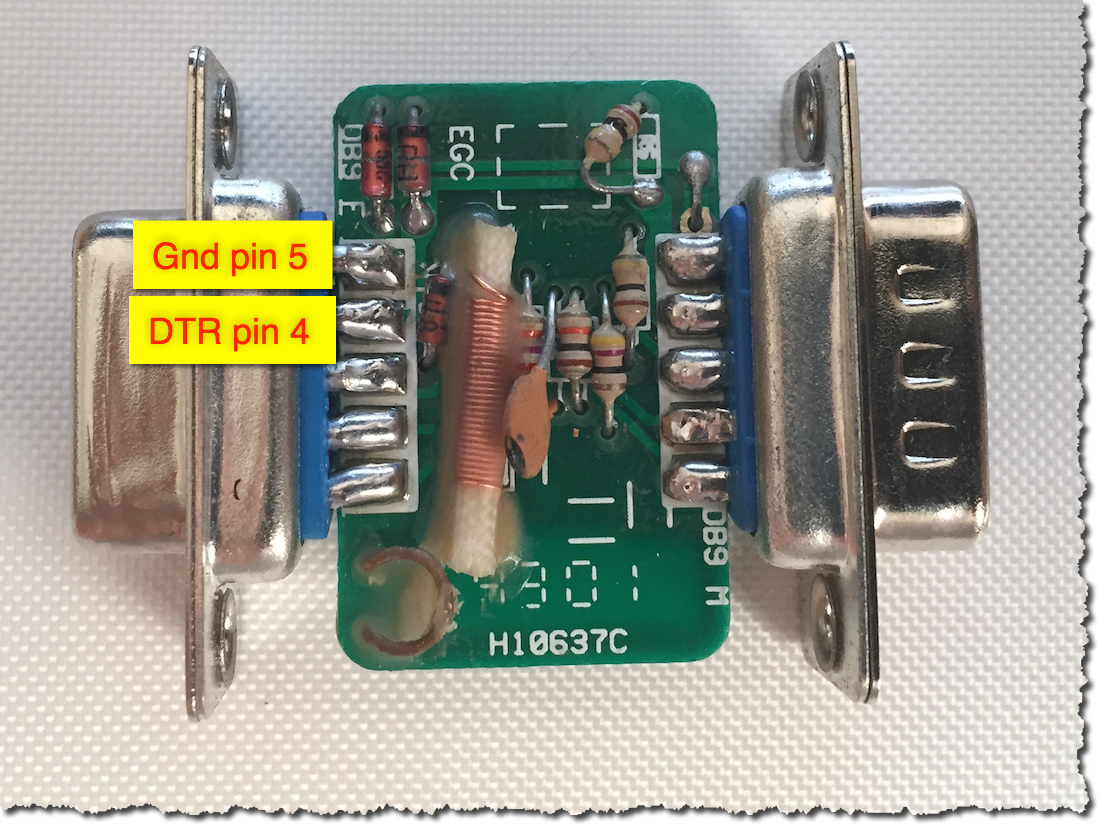
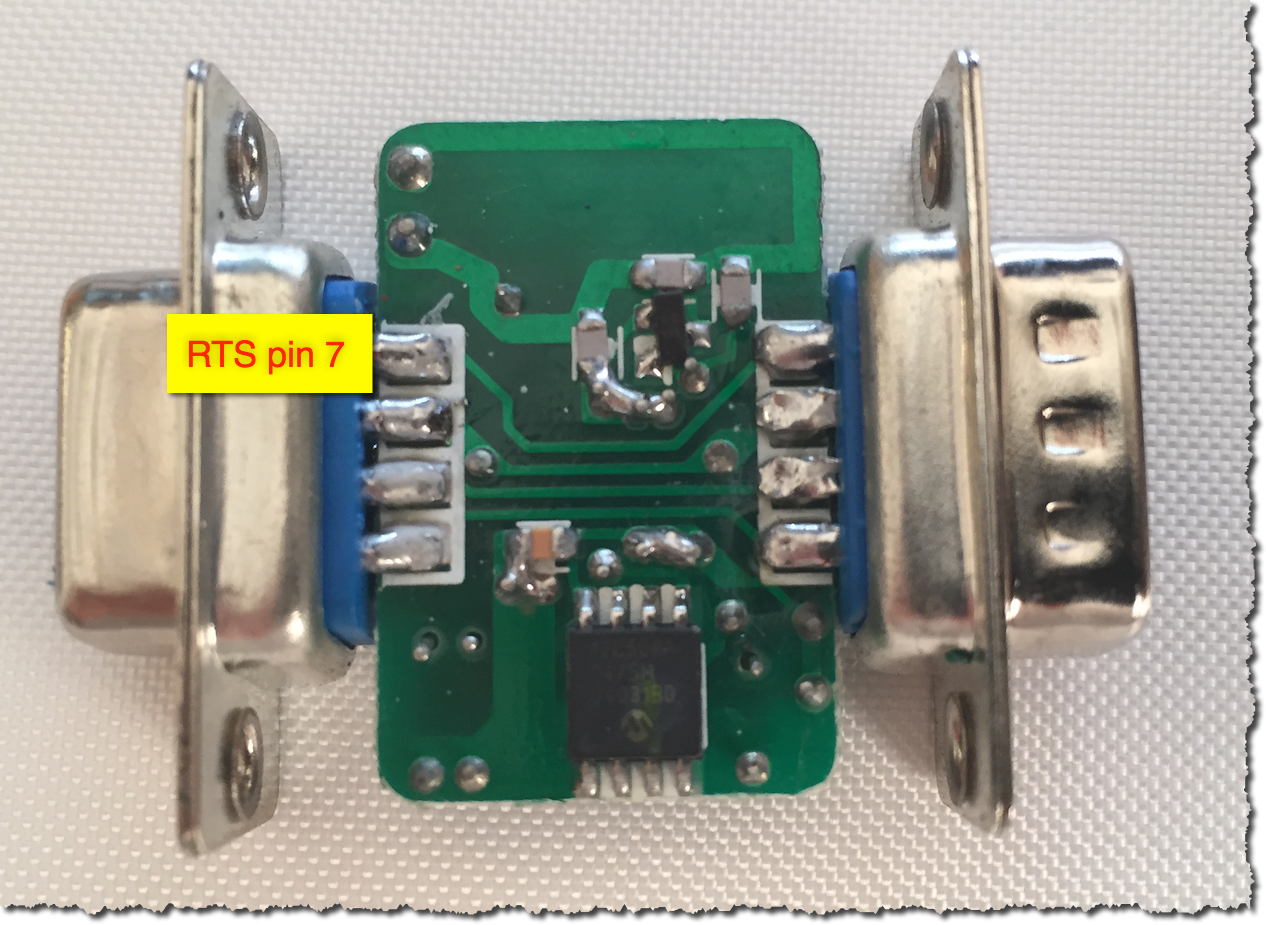
The breadboard version
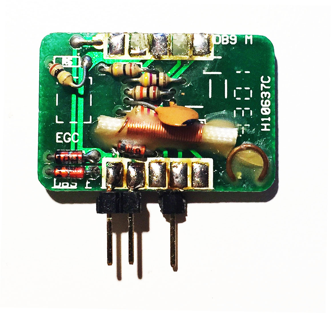
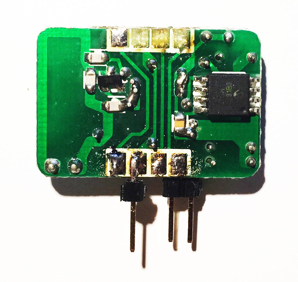
The build photographs also show the CM17A with its DB9 connectors removed and header pins fitted for the breadboard. The electrical connections remain the same; the annotated views below identify the three signals on the modified board.
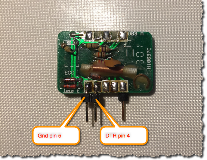
How the Arduino sketch works
The included sketch implements the transmission directly, without an external library include. Its xmitCM17A(house, device, command) function combines a house code, a device code, and a command, then sends a five-byte message. The house-code table covers A through P, and the device table covers units 1 through 16. Use those ranges when editing the examples, because the function indexes the tables directly.
Each message contains the header bytes 0xD5 and 0xAA, two data bytes, and the footer 0xAD. The sketch resets the interface with both outputs low, raises both outputs for standby, waits 35 milliseconds, and then sends the bits through RTS and DTR. It uses a 1 millisecond bit delay and a 500 millisecond pause after each transmission.
The Firecracker uses these control lines for power and signaling; it does not use the usual serial TX/RX data lines. The sketch’s Serial.begin(9600) is for diagnostic messages in the Arduino Serial Monitor. The ControlX10::CM17 documentation describes the same RTS/DTR signaling and 40-bit packet structure.
Try a simple command sequence
The archived loop() repeatedly sends two BRIGHT commands followed by four DIM commands on house code A. For a clearer first check, replace only loop() with the sequence below and keep the existing setup, lookup tables, and xmitCM17A() function. Set the receiving module to A2, or edit the house and device values to match your setup.
void loop() {
  xmitCM17A('A', 2, ON);
  delay(2000);

  xmitCM17A('A', 2, DIM);
  delay(2000);

  xmitCM17A('A', 2, BRIGHT);
  delay(2000);

  xmitCM17A('A', 2, OFF);
  delay(2000);
}
ON and OFF include the device number in the transmitted data. In this sketch, BRIGHT and DIM encode only the house code and command, so send ON to select the intended unit before adjusting brightness. The archive labels these as 20% steps; that label is not a measurement of the resulting lamp brightness. For an appliance module, use ON and OFF and omit the dimming commands.
Circuit reference
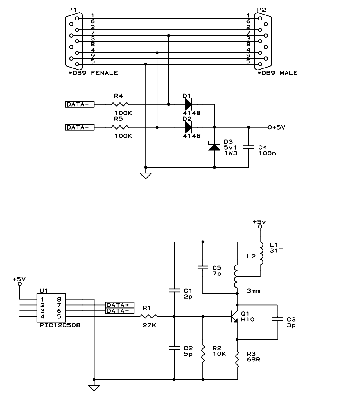
The supplied schematic provides a closer look at the Firecracker circuitry and its connector connections. Select the image to open the full-size reference.
Build photographs
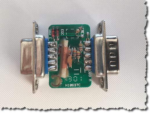
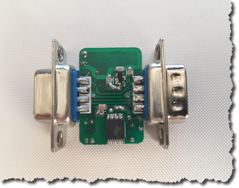
Additional views document the original board, the header-pin modification, and the completed lamp-control setup. Select any photograph to see it at full size.
Project resources
Arduino X10Firecracker Resources contains Arduino_To_CM17A_Resources.zip, with two archives:
Arduino_To_CM17A.zip— the Arduino sketch used for the CM17A interface.libraries.zip— the accompanying collection of Arduino libraries. The standalone CM17A sketch shown here does not include an external library.
The resource package will be available on Github
Shop listing coming soon.
The archived sketch credits BroHogan and is dated July 19, 2008. Wiring, timing, and command notes in this article are based on the supplied sketch and project photographs.